LED Constellations
- Charlotte biszewski

- Jul 18, 2021
- 4 min read
Updated: Aug 11, 2021
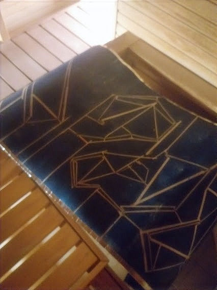
LED Constellations The final works of the PhD would be a series of LED light hanging pieces. I had decided a while ago to create a series of large light pieces - but it took almost the entire three years to decide upon and design the final format. I played around with the idea of integrating the LEDs directly onto the paper which was used for the woodcut prints (more details on creating the woodcut prints can be found in a previous post). However, I felt this would be too messy, and it would be difficult to get the compositions of inks and prints to work together. I also was interested in printing with fine Japanese papers, and it was quickly discovered that this had neither the rigidity to hold soldered electronics nor a smooth enough surface to have good conductivity with the ink. This was a shame, but I decided to get around this by overlaying the prints, and using the ink directly on plain blue paper.
If you look back at the 'Expanding the Max7219' post, you can see some earlier attempts at experimenting with different forms of creating light pieces. This was the original plan was to use a Max7219 – which can control up to 64 LEDs. Some initial sketches are below, notice the design often becomes complicated as the LED traces have to all link up - meaning that the lines have to continuously weave over and under each other:
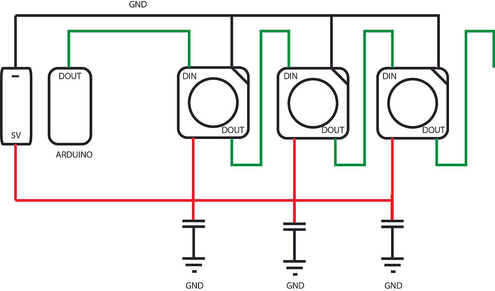
The designs for this was developed further to work on a larger scale. You can find the working circuit diagram and full sketch of the working model on my EasyEDA site. Later on, when searching for an electronics and interactive art specialist, I came across Synestetica Studio – a specialist in interactive light pieces based in Ukraine. They suggested I take a look at addressable LEDs - as they offer more control over the patterns in the lights, are more responsive and can add effects such as flitter and dimming. There are many instructables dedicated to addressable LEDs - their use and best practices. I found this adafruit guide to be the most useful. With addressable LEDS, a few issues new issues and considerations for the design arose, such as the need to connect each LED to the ground and +5V. It felt necessary to integrate this into the design, so a grid with ground running up one side, a 5V on the other was designed.

The control for the LEDs ran up the middle. This reflected the earlier idea of constellations, the grid of the star maps. The design finally began to ‘fit’ with its purpose. Below you can see the design for how the LEDs would work - the idea was that the data-line which runs from the Arduino to the LEDs in a line - would snake in and out of each page. You can see the front and back image for each star map below. This caused considerable issues with the planning. It means that the prints were double-sided and could be viewed from both sides.
In order to function well, these pieces also need to have a capacitor for each LED- a small SMD CAP104, - a larger capacitor placed every 5 LEDs caused power shortages for some LEDs- causing them to go a bit funny and give a mixed signal to all subsequent LEDs.

Here you can see this in action with an initial prototypes. Notice how many LEDs flash out of sequence. This was due to a wonky signal given off, as some LEDs were not receiving a consistent power.
PROBLEMS
When it came to creating the works at such a large size a number of issues arose. First problem - getting the lines onto the paper. The ink which I was using - which can be found in the inks posting, was screen printable, but as each constellation needed a different pattern, there did not seem much point in creating individual screens. After several attempts at creating stencils, using special light adhesive materials and more, magic tape was found not to damage the paper and create the smoothest line.

The second problem,
was heating up the ink. The ink used, like many silver conductive inks, needed to be heated - in this case it was to 100°C, which is not too hot. However, it needed a certain amount of time at this heat for the particles to 'sinter' (fuse together and become conductive - I think). I tried many things - hairdrying and ironing was painstaking and difficult to get an even amount of heating. I tried putting the prints into a sauna - which did not get hot enough - surprisingly. Air does not conduct heat very well, so even at 100°C, it wasnt hot enough.

It was a stroke of luck that I had seen someone in the studio next door with a giant laminator, I managed to borrow it off them in exchange for a crate of beer, and persuade the next door neighbours to lend me their forklift. I put it into the middle of the museum where I worked, stealing the power from one of our printing presses and for two weeks during lockdown I ran my final pieces back and forth through the laminator to get them hot enough.
That was all the major problems encountered, below you can find a quick step-by-step guide on how each piece was created:
MATERIALS
Paper: FABRIANO ACCADEMIA 200 g/m2 1,5 x 10 m
WS2812B-Mini LEDs x 120
1204 SMD CAP 104 X 120
Arduino Nano (or similar)
200ohm resistor x 1
1000uF Capacitor
1. The paper had to be coated in blue ink and dried. This was done with inking rags and rollers -using basic relief/letterpress ink.
2. The basic design was copied and marked onto the paper.
3. The individual pads for each LED was screenprinted onto the drawn lines.
4. The lines were connected with scotch tape - making sure each data-in line connected to the data out.
5. Protecting any previous lines with masking tape the vcc and gnd grid was added and a main vcc and ground line run up each side in aluminium tape.
6. The circuits were run through the laminator until the resistance of each line (including the very long lines) was less than 10ohms.
7. The LEDs and capacitors were glued and then soldered onto the paper.
8. The lines and connections were tested. Any shorts or misconnections fixed.
9. A wooden frame was built to keep the prints secure.
10. It worked!


Comments